- DCN Tutorial
- Data Comm & Networks Home
- DCN - Overview
- DCN - Computer Network Types
- DCN - Network LAN Technologies
- DCN - Computer Network Topologies
- DCN - Computer Network Models
- DCN - Computer Network Security
- Physical Layer
- DCN - Physical Layer Introduction
- DCN - Digital Transmission
- DCN - Analog Transmission
- DCN - Transmission media
- DCN - Wireless Transmission
- DCN - Multiplexing
- DCN - Network Switching
- Data Link Layer
- DCN - Data Link Layer Introduction
- DCN - Error detection and Correction
- DCN - Data Link Control & Protocols
- Network Layer
- DCN - Network Layer Introduction
- DCN - Network Addressing
- DCN - Routing
- DCN - Internetworking
- DCN - Network Layer Protocols
- Transport Layer
- DCN - Transport Layer Introduction
- DCN - Transmission Control Protocol
- DCN - User Datagram Protocol
- Application Layer
- DCN - Application Layer Introduction
- DCN - Client-Server Model
- DCN - Application Protocols
- DCN - Network Services
- DCN Useful Resources
- DCN - Quick Guide
- DCN - Useful Resources
- Selected Reading
- UPSC IAS Exams Notes
- Developer's Best Practices
- Questions and Answers
- Effective Resume Writing
- HR Interview Questions
- Computer Glossary
- Who is Who
Multiplexing in Computer Network
Multiplexing is a technique by which different analog and digital streams of transmission can be simultaneously processed over a shared link. Multiplexing divides the high capacity medium into low capacity logical medium which is then shared by different streams.
Communication is possible over the air (radio frequency), using a physical media (cable), and light (optical fiber). All mediums are capable of multiplexing.
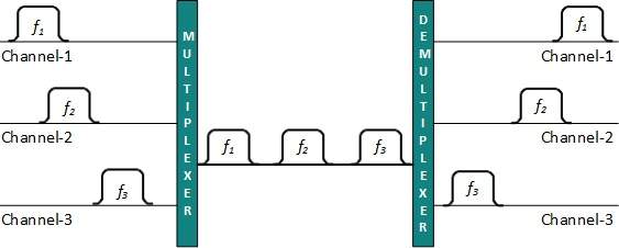
When multiple senders try to send over a single medium, a device called Multiplexer divides the physical channel and allocates one to each. On the other end of communication, a De-multiplexer receives data from a single medium, identifies each, and sends to different receivers.
Frequency Division Multiplexing
When the carrier is frequency, FDM is used. FDM is an analog technology. FDM divides the spectrum or carrier bandwidth in logical channels and allocates one user to each channel. Each user can use the channel frequency independently and has exclusive access of it. All channels are divided in such a way that they do not overlap with each other. Channels are separated by guard bands. Guard band is a frequency which is not used by either channel.

Time Division Multiplexing
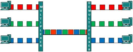
TDM is applied primarily on digital signals but can be applied on analog signals as well. In TDM the shared channel is divided among its user by means of time slot. Each user can transmit data within the provided time slot only. Digital signals are divided in frames, equivalent to time slot i.e. frame of an optimal size which can be transmitted in given time slot.
TDM works in synchronized mode. Both ends, i.e. Multiplexer and De-multiplexer are timely synchronized and both switch to next channel simultaneously.

When channel A transmits its frame at one end,the De-multiplexer provides media to channel A on the other end.As soon as the channel A’s time slot expires, this side switches to channel B. On the other end, the De-multiplexer works in a synchronized manner and provides media to channel B. Signals from different channels travel the path in interleaved manner.
Wavelength Division Multiplexing
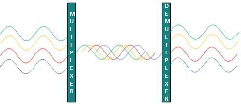
Light has different wavelength (colors). In fiber optic mode, multiple optical carrier signals are multiplexed into an optical fiber by using different wavelengths. This is an analog multiplexing technique and is done conceptually in the same manner as FDM but uses light as signals.

Further, on each wavelength time division multiplexing can be incorporated to accommodate more data signals.
Code Division Multiplexing
Multiple data signals can be transmitted over a single frequency by using Code Division Multiplexing. FDM divides the frequency in smaller channels but CDM allows its users to full bandwidth and transmit signals all the time using a unique code. CDM uses orthogonal codes to spread signals.
Each station is assigned with a unique code, called chip. Signals travel with these codes independently, inside the whole bandwidth.The receiver knows in advance the chip code signal it has to receive.